
Hall Effect: Definition, Principle, Measurement Methods
Ⅰ. What is the Hall Effect?
The interaction of the matching electric and magnetic fields of charged particles, such as electrons, results in the Hall effect. The Hall effect principle is illustrated in the following animation for a clearer understanding.
Ⅱ. Hall effect principle
Current starts to flow when the conductive plate is linked to a circuit with a battery. From one end of the plate to the other, the charge carriers will move in a straight line. A magnetic field is produced by the passage of charge carriers. The magnetic field of the charge carriers is altered when the magnet is put close to the plate. The straight-line flow of charge carriers is hampered as a result. The Lorentz force is the force that alters the direction of the flow of charge carriers.
Positively charged holes will be deflected to one side of the plate and negatively charged electrons will be diverted to the opposite side of the plate as a result of the distortion of the charge carrier magnetic field.The Hall voltage, which may be measured using a meter, is the potential difference that is produced between the two sides of the plate.
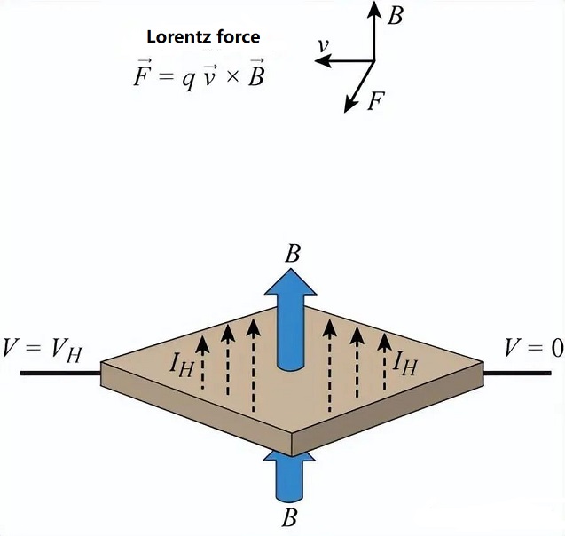
The magnetic field perpendicular to the conducting plate is represented by blue arrow B in the Hall effect and Lorentz force equation.
According to the Hall effect concept, a voltage can be measured where the current path is at a right angle when a current-carrying conductor or semiconductor is inserted into a vertical magnetic field.
The following formula yields the Hall voltage, written as VH:
Hall Voltage Formula:
On the conducting plate, VH stands for the Hall voltage.
The sensor's current is denoted by the symbol I.
The magnetic field intensity is B.
The charge is q.
The number of charge carriers per volume unit is n.
The sensor's thickness is d.
Principle of Hall Effect Sensors
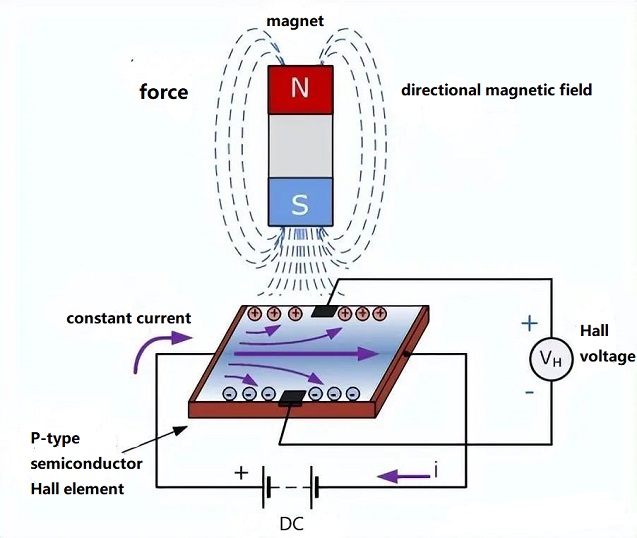
The sensor detects it and generates an output voltage known as the Hall voltage VH when the magnetic flux density in the area surrounding the sensor reaches a certain threshold. The ensuing figure illustrates the particular principle.
A small rectangular slice of p-type semiconductor material, such as gallium arsenide (GaAs), indium antimonide (InSb), or indium arsenide (InAs), that carries a continuous current is the basic building block of a Hall-effect sensor.
Ⅲ. Hall Effect Sensor Schematic
The magnetic flux lines acting on the semiconductor material in a Hall-effect sensor cause charge carriers, electrons, and holes to be deflected to either side of the semiconductor plate. The magnetic field that charge carriers encounter as they go through the semiconductor material is what causes this movement.
Due to the accumulation of these charge carriers when the electrons and holes flow sideways, there is a potential difference between the two sides of the semiconductor material. An external magnetic field at right angles to the semiconductor material then affects the flow of the electrons through it; this effect is stronger in flat rectangular materials.
The magnetic field's strength and the sort of magnetic pole are both revealed by the Hall effect. For instance, a south pole would result in a voltage output from the device, whereas a north pole would have no impact. In the absence of a magnetic field, Hall effect sensors and switches are typically built to be "off" (open circuit states). They can only "open" (become closed-circuit) when exposed to a magnetic field with enough power and polarity.
Ⅳ. Hall Effect Sensor
The sensor functions as an analog sensor in its most basic form, directly returning voltage. Its separation from the Hall plate can be calculated with the aid of a known magnetic field. The relative position of the magnets can be determined using the sensor set.
Hall effect sensors are frequently used in conjunction with circuitry that enables the device to operate in digital (on/off) mode; in this arrangement, they may be referred to as switches. The change in light is readily visible in the image below, which depicts a wheel holding two magnets moving through a Hall effect sensor.
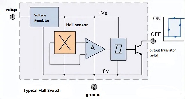
Because most Hall effect devices only have a very tiny output drive capacity-between 10 and 20 mA-they are unable to switch big electrical loads directly. Add an open collector (current sinking) NPN transistor to the output for high current loads. As displayed below
When the applied magnetic flux density is greater than the "ON" preset value, the transistor behaves as an NPN sink current switch, shorting the output terminal to ground.
Relays, motors, LEDs, lights, and other loads can all be driven directly by the output switching transistors in a push-pull output configuration whether they are configured as open-emitter transistors, open-collector transistors, or both.
Linear or digital outputs are provided for Hall-effect sensors. The output voltage of a linear (analog) sensor is proportional to the magnetic field passing through the Hall sensor, and the output signal is directly obtained from the output of the op amp. The Hall voltage at the output is:
Hall voltage is expressed in volts as V H.
The Hall effect coefficient is R H.
I is the amount of current (in amps) passing through the sensor.
T is the sensor's thickness in millimeters.
B is the magnetic flux density for Tesla.
A continuous voltage output is produced by linear or analog sensors, and it rises in the presence of powerful magnetic fields and falls in the presence of weak ones. As the magnetic field intensity rises in a linear output Hall effect sensor, the output signal from the amplifier rises as well until the supplied power supply's constraints cause it to saturate.
Any further expansion of the magnetic field will saturate the output further rather than having any impact on it.
Latest Products

- IP5002CX8/P135 NXP USA Inc.

- ADAU7002ACBZ-RL Analog Devices Inc.

- PGA2320IDW Texas Instruments

- SRC4184IPAG Texas Instruments

- MUSES72320V-TE2 Nisshinbo Micro Devices Inc.

- PCM2706CPJT Texas Instruments

- ZL38040LDG1 Microchip Technology
- PGA2310UA/1K Texas Instruments